Hello IoTIAN in this blog we create a PCB Schematic on
Autodesk Eagle. Autodesk Eagle is PCB design software. Which is very good for
creating professional pcb for your IoT project.
Now we create only schemetic design of PCB and in next blog
we convert this schematic into PCB. There are few steps for creating schematic.
So let’s start with Autodesk Eagle:
Before starting first create a rough schematic of your PCB
on paper:
Step:1 Download
Autodesk Eagle from this link: autodesk.com/products/eagle/free-download
Step:2 After downloading Autodesk Eagle install it in your
machine and open it. This default screen is automatically open.
Step 3: After that go to left side of this screen and right
click on Projects:
Step 4: After click on projects click on new project
Step 5: Give any name to your project
Step 6: After that right click on that project Go to
New-> Schematic
Step7 : After that this schematic window is open
Step 8: After that click on add part on left side for add
frame on schematic window:
Step 9: Choose the frame from the given list:
Step 10: Like the frame add all the part of your schematic
using add part tab:
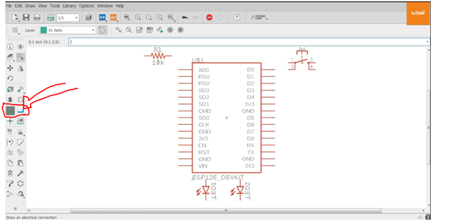
Step 11: After adding all parts of your schematic connect
these components together using net tab on left side:
Step 12: And connect all the components together:


Comments
Post a Comment